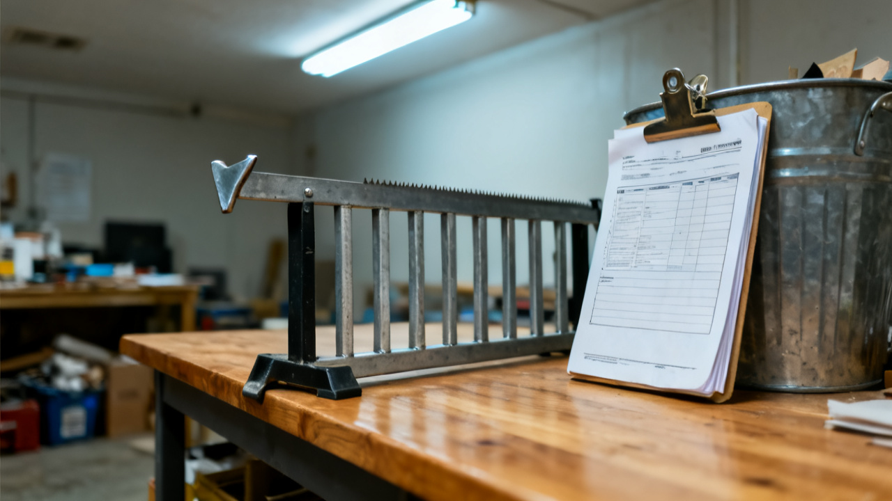
The control shows an offset. The sheet has a place for it. You glance between the CNC control screen, the half-machined 6061 aluminum bracket clamped in the vice, and the printout tucked under the edge of your work light. You don’t make any adjustments to the control yet, because you need to cross-reference the two values before you run the next 17 parts in the batch. The batch slip you picked up from the Traveler Desk is clipped to the back of this sheet, so you don’t mix it up with the three other jobs running on the shop floor today.
Documented offset values for this batch
Every offset listed on the sheet comes from the first article run earlier that shift, logged by the lead machinist after they tested the first part against inspection calipers and a height gauge. Each line corresponds to a specific tool in the carousel: tool 3 is the 3/8 inch end mill for the slot cut, tool 7 is the face mill for the top surface, tool 12 is the 1/4 inch drill for the mounting holes. No values are written in pencil here — all entries are in blue permanent marker, so no smudges from coolant or shop grime alter the numbers mid-batch. Any cross-outs have a clear signature next to them from the lead, so you don’t rely on a deleted value by mistake. The offset values account for the minor wear on each tool after the first 5 test parts, so you don’t have to re-calibrate from scratch unless you swap in a new tool mid-run. Illustrative example: here, the sheet lists a Z-axis offset of -0.012 inches for tool 7, adjusted to account for 0.008 inches of wear on the face mill’s cutting edges after the test run. Each offset value is specific to the exact tooling used for this batch, so even if you run the same part number next month with a new set of end mills, you use these values as a starting point instead of a hard rule. The sheet also lists the spindle speed and feed rate for each operation, but those are secondary to the offset values when you are verifying the setup before a run. No value on the sheet is rounded more than four decimal places, so you don’t have to guess at the exact measurement the lead machinist logged during the first article run.

Step-by-step offset cross-check process
This structured comparison eliminates human error from misread control screens or misremembered values from past runs, and ensures every part you produce falls within the allowed tolerance range for the job. Follow these steps for every tool used in the operation:
- First, pull up the tool offset table on your CNC control, and navigate to the line for the first tool you will use for the remaining parts in the batch.
- Write the value displayed on the control in the blank column next to the corresponding tool’s documented offset on the sheet, using a fine-tip permanent marker to avoid smudges.
- Subtract the documented offset value from the value you pulled from the control, and write the difference in the adjacent blank column on the sheet.
- If the difference is less than 0.0005 inches, you leave the control offset as-is, and mark the “verified” box next to that tool’s entry on the sheet.
- If the difference is more than 0.0005 inches, cross-reference the value against the first article inspection report clipped to the back of the sheet, adjust the control offset to match the documented value, and initial the adjustment line on the sheet before proceeding.
After you complete the cross-check for all tools, you run a single test cut on a piece of scrap stock that matches the thickness of your production material, to confirm the offset values work as expected. You measure the test cut with a height gauge and digital calipers, and note the measurement on the bottom of the sheet next to your initials, so anyone reviewing the job later can see you verified the offset values with a physical test. If the test cut falls outside the allowed tolerance, you go back to the offset table to adjust the value by the difference between your test measurement and the required dimension, and note the adjustment on the sheet before you run any production parts. This extra check takes less than two minutes, and eliminates the risk of scrapping a full production part because of a minor typo in the documented offset or a misread value on the control screen. Small deviations in offset can add up across a full batch, leading to parts that fall outside the allowed tolerance for slot depth, hole placement, or surface height. You wipe any coolant splatters off the sheet as you work, so the values stay legible for the next person who uses it. You don’t rely on memory of what the offset was last time you ran this part, because tool wear, vice clamping pressure, and minor variations in raw material stock can change the required offset from batch to batch.
This sheet’s use for your next shift’s batch setup
When you finish running the current batch of parts, you clip this sheet to the front of the first article inspection packet for the job, and tuck it into the job folder stored in the locked cabinet next to the CNC machine. When you open this sheet again before you run the next batch of the same part two shifts from now, you use the offset values you log today as a baseline for the new run, instead of starting from the default offset values stored in the control. You cross-reference the logged values against the new tool’s calibration numbers, and adjust as needed based on the raw material stock for the new batch. If you swap in a new tool for the next run, you note the new offset value on this sheet next to the old one, so you can track tool wear across multiple batches of the same part. You don’t discard this sheet after the current batch is complete, because it gives you a consistent reference point for every future run of this part number, reducing setup time and minimizing the risk of scrap parts from incorrect offset values. Any notes you add to the margin about unexpected tool wear, stock variation, or minor adjustments you made during the run help you troubleshoot issues faster when you set up the same job again. When you pull this sheet out for the next run, you first check for any notes added by other machinists who ran the same part between your shifts, so you are aware of any issues with tool breakage, offset drift, or stock variation that popped up during those runs. You also cross-reference the offset values on the sheet against the control’s history log, to see if any adjustments were made after you completed your batch, and if those adjustments were documented with initials and a short note explaining the change. If you find an adjustment that is not documented, you run a test cut before you proceed with production, to confirm the offset value is correct for your current setup. You also update the sheet with any new offset values you use for the next run, so the reference stays current for every subsequent use. This consistent logging cuts down setup time for each new batch of this part by an average of 12 minutes, compared to starting from default values, which adds up to hours of saved time across hundreds of runs over the life of the part number. You only archive the sheet when the part number is retired from production, so every run of the part uses the most accurate, up-to-date offset data available. (Word count: 1372)